VK5RDX 53.750MHz Fm repeater filter
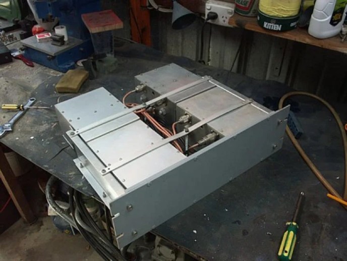
Back in 1993 I want to build a 6m repeater to play with on FM, We just didn’t have a repeater in the Adelaide area at the time.
I was in the South Coast Amateur Club at this stage and that gave me the opportunity wit the clubs blessing to install a repeater on their Chandlers Hill site. The deal was we also build a 70cm repeater that Peter VK5TZX lead.
One part of the repeater system is the antennas. Do I use one or two antennas.
The main disadvantage of two antennas is the cost of two of everything.
One problem with a single antenna or two was I still needed a filters, the TX and RX frequencies are only 1MHz apart.
This filter project started because some said it can’t be done. Don’t every say that to me 🙂 it’s like calling Marty Mc Fly chicken. (back to the future)
How Hard could it be, Ha Ha
I read the ARRL hand hook etc but there was a lack of information, places like RFI did plenty of R&D that was a secret to us mir mortals. The gold mine was a book called the filter synthesis hand book. its a big book that weighs a few kilograms.
6 months of playing around doing the maths and building photo types to get what I needed in isolation. Lots of used coax and scrap copper in the bin trying all sorts of designs. and the 4 hours of sleep before going to work each day. But its ham radio and I loved it.

Some of my designs I melted as I used acrylic helical pipe former from RF heat losses. The photo right shows 4 helical filters inside 100mm copper pipe. A 3mm wire was wound around acrylic tubes to form the helical.
I also did try coaxial 1/4 notches, that was a fail.
Many other designs I could not get to tune or they were very touchy to tune.
These two photos below show my third design using the larger square helical cavity to get more Q. I made them from copper for easy soldering. Square shapes are also easier to work with with my limited tools. You can see also home made brass nut, stud bolt where the helical coil is mounted.


I ended up using aluminum for weight and cost. The prototype was mostly copper.
The cavity box’s I bend up was with a new pan brake bender I made for the job. The helical mounting bolts and nuts I turned my self out of aluminum hex stock. Yep I loved metal work. I didn’t want dis-similar metal corrosion. if you design the cavities correctly the cover caps don’t change the tuning.

I anodized the box sections my self at home to protect the surface and reduce losses.
Anodising aluminum surface is very easy and finishes the cavities really nice. The process is Just using caustic soda and electricity, then once done pour boiling hot water over the surface to seal it. These photos above are taken off the filters after 8 years of service, they still look new. I anodize most of my projects. Note the extension joins on the coil ends. This is to fine tuning the filter with out effecting the Q too much.
The helical coils are made from 6mm copper tube. Easy to bend and light weight. I never tried aluminum tubing as it was too hard to find, the losses may be higher too. The copper tube was polished before they were rolled into shape. After I soldered the bolts to the coils I dipped them in clear lacquer.
The original version of this design used copper bar, this would work too harden as I bent the bar around a mandrel.
Below are the helical units as a complete duplexer unit. This configuration has one transmit filter and 3 receiver filters.

This filter gave me the isolation I needed for 25Watts on transmit with no de-sence on the receiver.
Double shielded Teflon coax was used between the sections, the coupling harness the same coax. This reduces RF leaks.
I found out while testing the helical’s were a little microphonic, I reduce this to minimal by place Styrofoam spacers between the cavities box walls and coils. This stopped all movement and fixed the problem.
The reason I didn’t use a former inside the coils was losses. I did measure quite a few dB of losses in my trials with coils former which cause the Q to drop. with todays technology I could 3D print some spacers I guess.
At some stage I will go through my notes and draw up some plans to show how to make them, its been years so good luck to my self. I did find them now (2026) and will have to work out my thinking 🙂
AREG wanted more power so in 2009 the filter were upgraded to cavity filters. The Cavity duplexer were designed and built by AREG members Peter VK5TZX and Graham VK5GH, they used helical loaded cavity. 1.5m high was short as they were helically loaded at the ends. We new had the rack space. The higher power rating and the less losses are down from 2.3dB to 1.2dB. That’s a big improvement on the transmit side.
My secret weapon
As I said before the Handbook of Filter Synthesis, chapter nine has a helical filter design section. I forgot who lent me the book, I copying the whole book. This book was too expensive for me at the time. Plenty of good advice from my friends helped the most. Sometimes you need different point of view to find a solution.
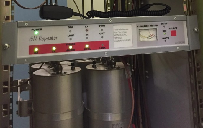
My test equipment was quite crude at the time. I had a analogue GW signal generator then upgraded to a Marconi analogue service monitor, an Electronic Australia spectrum analyser kit using my old CRO. A home made stepped attenuator was the key in calibrating the spectrum analyser this was a project in it own right. I would manually plot my results on paper.
After this project I got keen and started on a 10m repeater Duplexer with a 100Khz split, But I gave up after many hour of playing. I got down to 250kHz split, the Q was crazy high!! The 10m Repeater ended getting a split site so it wasn’t needed. If get really bored one day I may give it another try, the maths said it’s possible with enough Q. Getting this Q stable is the biggest problem.
Looking in my filing cabinet I found my original repair manual I wrote for my 6M repeater. It was written for the Mt Gambier home brew competition. I won it that year so it gives me fond memories, I never though I would win as the talent in the ham radio community is staggering.
I have taken this out of the filter section of the servicing manual I wrote in 1996

The Duplexer
The purpose of the duplexer is to combine the transmitter and receiver into a single antenna and isolate each other with minimal losses. One antenna was the least costly solution as lightning protection and one coax run is much cheaper.
Two separate antennas can be use with out a duplexer but the separation of the two antennas is to hard to obtain 90dB isolation is needed. A split site would be needed which is not practical and costly. Coverage disparity is a major problem for separate-site repeater antennas. The transmitter and receiver coverage areas overlap.

Helical Filters
I chose this method because of its size, ease of construction and replication. The design uses three individual two pole filters for the receiver path and one two pole filter for the transmit path. Each pole has approximately a Q of 1800. (a third filter is used in the receiver path as a temperature stability safety margin)
Each filter pole resemble a coaxial quarter—wave resonator, except that the inner conductor is in the form of a single—layer solenoid or helix. The helix is enclosed in a highly conductive shield of square cross-section. One end of the helical winding is connected directly to the shield and the other end is open circuit. Coupling into the filter is via tap coupling, this type of coupling has construction advantages as well as offering necessary stability in order to satisfy shock and vibration specifications. The position of the tap is approximately calculated and the exact position is experimentally determined at the test bench for best matching.
The coupling of the helical resonators is via a aperture window, the size of this window has been experimentally adjusted on the test bench to get maximum energy transfer with out effecting the Q. The window is in the lower part of the partitions providing mostly inductive coupling, the filter exhibits more attenuation on the high- frequency side of the response.
The filters have a anti-resonate element fitted to them. These elements are added to get the required 1MHz split needed, with out these elements the filters Q is much too low, isolation between TX/RX would be minimal.
When a reactance is connected across a series resonant circuit, an anti-resonant notch is produced, the resonant frequency is shifted. A high voltage capacitor is fitted across the transmit filter which causes the notch to appear below the resonant frequency. The receiver filters have an inductor across them causing the notch to appear above the resonant frequency. The value of capacitor and inductor determines the spacing between the notch and resonant
The 52.750MHz receiver filters are connected together in cascade with short (lengths of coax. the attenuation at 53.750MHZ is greater than 180dB and insertion loss at 52.750MHz is less than 0.5dB. The 53.750MHZ transmit filter attenuation at 52.750MHz is greater than 60dB and insertion loss at 53.750MHZ is less than 2.2dB.


Of cause some of these measurements are not realistic with the coaxes that ay leak a bit or even the repeater leaks. Shielding is the biggest issue. We have a scratchy receiver issue for month even with the new cavity filters. It ended up being a loose bolt on the tower. The repeater has been running since 1994 and only the antenna has been damaged by lightning and the external power 50watt amplifier failed due to my mistake in interstage matching.
Fun fact, the Power amplifier is a modified Philips FM828 power PA, tuned down to 14watts to cope with hours of constant transmission.
When I find my old drawings and calculation I will write a construction page on this topic.
( I found them but need the time to sit down and write this up.)
73’s Adrian
I made a full size 6m BPBR cavity 2 of them, each of them 9 Folgers coffee cans with some good success. I used a 1/2 inch copper pipe for the 1/4 wave resonator. (Won’t go into details how I tuned it) Used 2 antennas (Ringo Cushcraft) about 50 ft apart. My split was 1.7mhz. A VHF Eng Xmtr @ 10 watts and a Motorola Mortrac Rcvr was used. Not bad results, all for fun and experiment. KA9DSL
Congratulations on taking on this challenge and for getting it documented. I am also interested in establishing a 6m repeater for my locality (Grafton, northern NSW).
Hi Brad, thanks for the comments. Sorry I just read your message through the sea of bogus comments. Good luck with the repeater project.